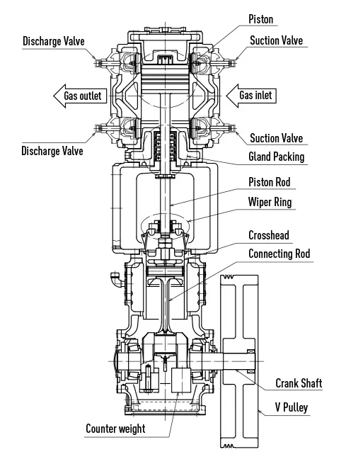
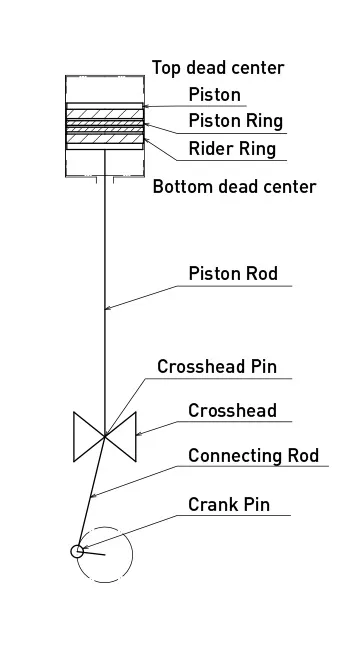
Basic structure of reciprocating compressor.
Rotating movement of motor is transformed to reciprocating movement through crank shaft and connecting rod. This movement gives reciprocating movement to piston and make the gas in cylinder compressed.
Formula of piston displace amount is as follows;
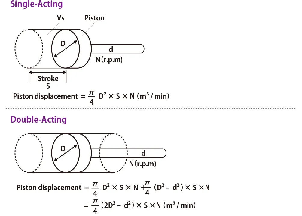
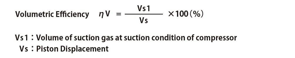
Volumetric Efficiency (ηv) is the numerical value to indicate how much percentage of piton displacement is actually discharged. Piston displacement represents cylinder stroke amount per unit time.
Theoretical Volumetric Efficiency can be shown as following formula;
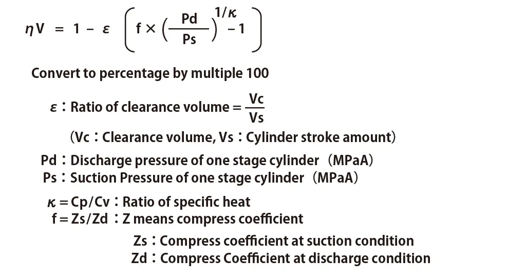
Actually, κ in the above formula is cooled down by cylinder etc. and it becomes polytropic compression and polytropic index “n” is used.
n: polytropic index (it is expansion coefficient of gas which remains at clearance volume and changed by cylinder cooling system and its capacity)
When design is done, loss have to be considered as well as “n” value since valve loss, gas leak from rings and/or pipe loss is expected.
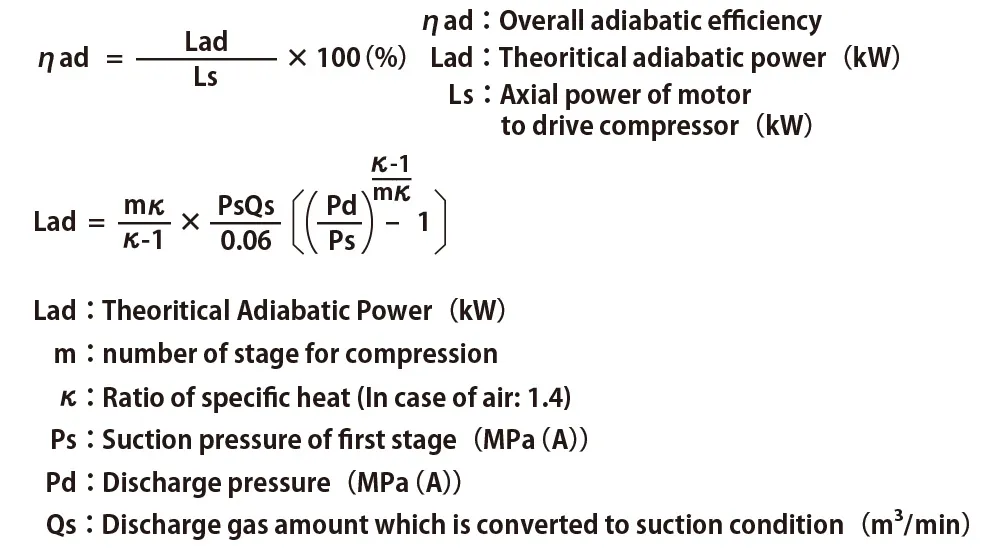
Power of compressor is decided by several factors including gas resistance of valve, flow channel, piping, machine loss, cooling quality, etc.
Including those factors, to indicate how much power is actually required is shaft power(Ls). Overall adiabatic efficiency shows the ratio of shaft power to the critical adiabatic efficiency.
By using the formula, calculation of necessary theoretical adiabatic power to compress 1m3/min of air under the normal condition. The result is shown on the table below. From the table, two stage compression requires less power to compare with one stage compression.
| Discharge pressure MPa (G) |
First stage Compression (kW) |
Second Stage Compression (kW) |
Discharge Pressure MPa (G) |
Second stage Compression (kW) |
|---|---|---|---|---|
| 0.05 | 0.7177 | 1.1 | 5.0087 | |
| 0.1 | 1.2810 | 1.2 | 5.2021 | |
| 0.15 | 1.7516 | 1.3 | 5.3831 | |
| 0.2 | 2.1593 | 1.4 | 5.5533 | |
| 0.25 | 2.5211 | 1.5 | 5.7141 | |
| 0.3 | 2.8478 | 1.6 | 5.8665 | |
| 0.35 | 3.1467 | 1.7 | 6.0114 | |
| 0.4 | 3.4227 | 3.0334 | 1.8 | 6.1496 |
| 0.45 | 3.6796 | 3.2366 | 1.9 | 6.2817 |
| 0.5 | 3.9205 | 3.4245 | 2.0 | 6.4082 |
| 0.55 | 4.1474 | 3.5994 | 2.1 | 6.5297 |
| 0.6 | 4.3622 | 3.7632 | 2.2 | 6.6465 |
| 0.65 | 4.5664 | 3.9173 | 2.3 | 6.7591 |
| 0.7 | 4.7610 | 4.0628 | 2.4 | 6.8677 |
| 0.75 | 4.9472 | 4.2008 | 2.5 | 6.9727 |
| 0.8 | 5.1257 | 4.3319 | 2.6 | 7.0742 |
| 0.85 | 5.2972 | 4.4570 | 2.7 | 7.1726 |
| 0.9 | 5.4542 | 4.5766 | 2.8 | 7.2680 |
| 0.95 | 5.6219 | 4.6911 | 2.9 | 7.3606 |
| 1.0 | 5.7760 | 4.8011 | 3.0 | 7.4507 |
This table shows theoretical power for the case adiabatic compression is done to free air which is 1m3/min.
The condition of overall adiabatic efficiency is important value as it directly impact to power consumption. Therefore design of more efficient machine from view point of friction of each sliding portion like machine structure, valve configuration, position, ring shape etc.
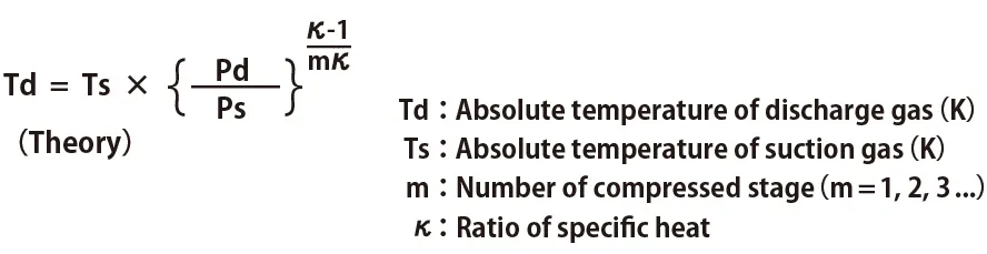
Theoretically, when heat transfer between compressor cylinder and outside is not done, all power for compression(machine energy) is used to raise temperature of gas. If it is theoretically adiabatic compression, theoretical temperature of discharged gas is calculated as following theoretical formula.
For reference, relation of pressure ratio and compression temperature in case ratio of specific heat is 1.4 at 1st stage compression is as follows:
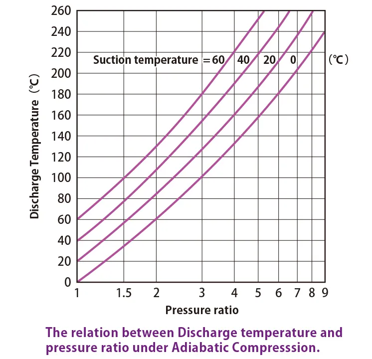
Actually, κ in the above formula is cooled down by cylinder etc. and it becomes polytropic compression. It becomes lower temperature than theoretical temperature. The ratio of falling temperature is affected by cylinder cooling system and its capacity, compression ratio, rotating speed, cooling water temperature, external temperature, amount of cooling water, valve characteristics, size of machine etc.
Compression ratio is Pd/Ps=(0.7+0.1013)MPaA/0.1013MPaA=7.9 and which temperature I shown as 256℃ from above table when atmospheric air which temperature is 20℃ is suctioned by one stage general compressor and boosted to 0.7MPag. But actual temperature becomes 170 to 190 ℃. Because the value of ratio of specific heat κ becomes 1.25 to 1.3 by cooling.